
The Keyboard - Part 3 : The Enwire-en-ing
In which too much time is spent poring over diagrams with coloured lines.
On Aesthetics and Procrastination.
IN THEORY, connecting a keyboard matrix up to a microcontroller is a simple job. You have X rows and Y columns, so you need X+Y pins on the microcontroller, and you wire up each row and column to a pin, making sure to avoid all the obvious GND/VCC etc pins. Also apparently the pin on this specific microcontroller that’s connected to the internal LED. Woops.
I also wanted to leave a couple of pins free for I²C devices for experimentation purposes if the fancy took me. I got a Teensy LC, ARM M0+ only 8K RAM but crucially, 27 IO pins, more than the 21 I needed to wire up the keyboard matrix. There are a couple of other more powerful models.

So, IN THEORY a simple job. I wanted it to LOOK good too, so spent far too much time messing around in inkscape drawing different layouts. Initially I had planned to route the column and row connections down between the keys and underneath the existing wires. I tried various different MC position and layouts.
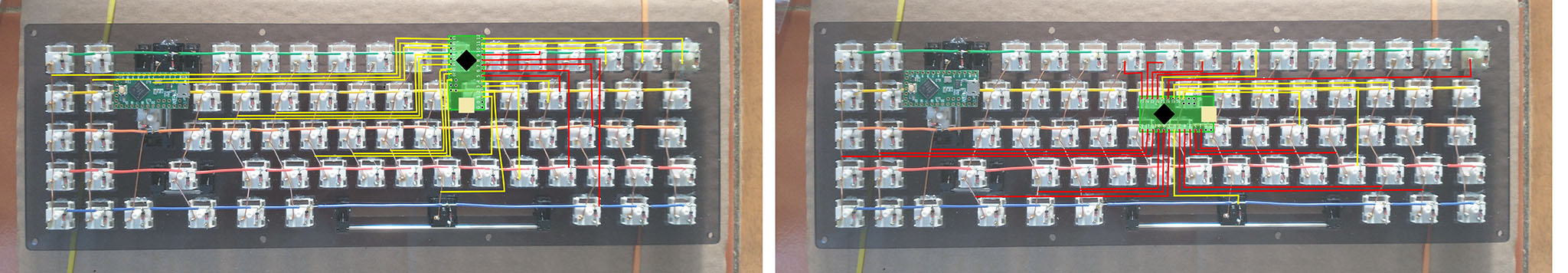
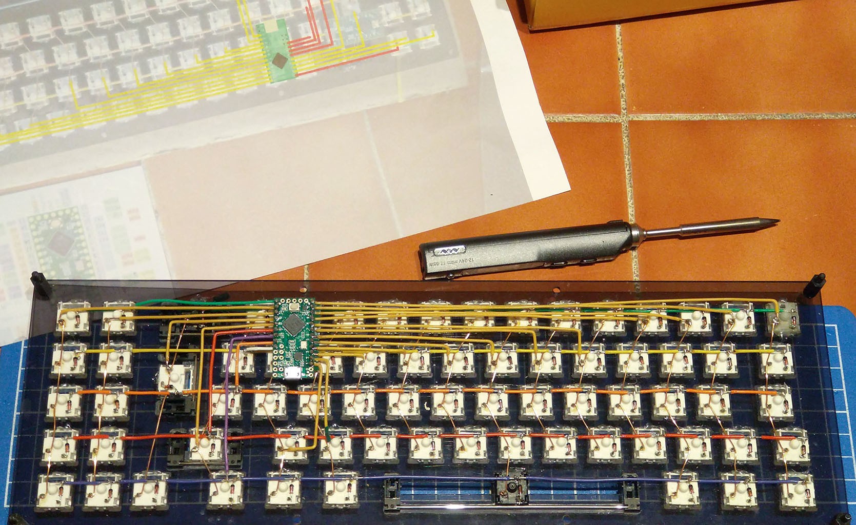
Ultimately I got bored drawing pictures and just routed the connections directly from the Teensy pins to specific locations on the row and column wires, but over the existing connection matrix. This was a lot simpler, I decided on the following plan:
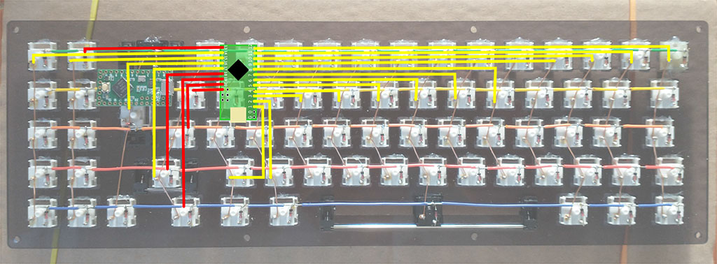
The Micro USB connector, the observant reader will note, is pointed down. More on this in a bit.
Let The Wiring … BEGIN
I figured fairly early on that actually measuring and cutting/bending/stripping the wires first, then soldering them into the Teensy, and only THEN soldering the entire thing onto the existing Matrix was probably the best bet. I did it in batches of 6 or 7 over the course of a couple of evenings:
With all of them being complete and ready for soldering into the Keyboard:
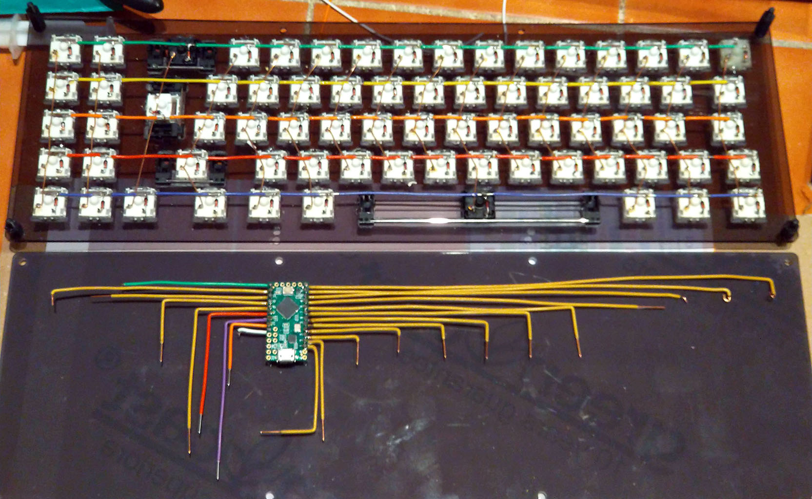
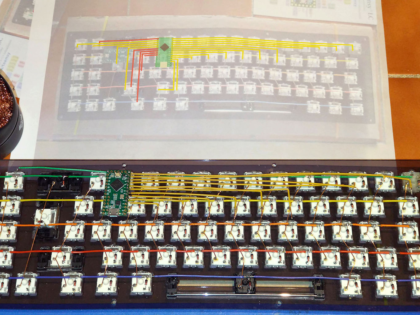
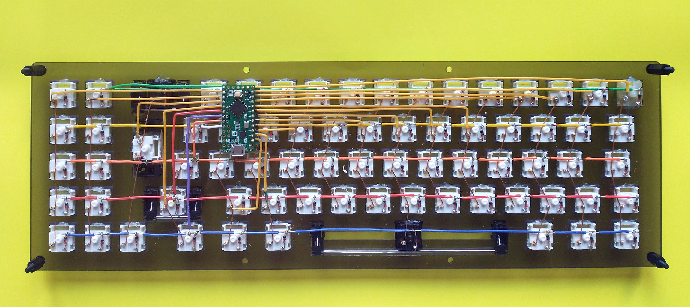
The Column connections were all yellow, the 5 row connections more or less matching the colours of the individual rows.
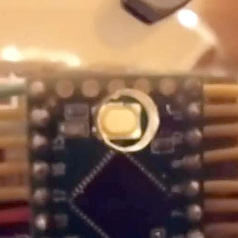
And a closeup of the Teensy in place, all wires soldered in. You can see the differently coloured row connections soldered into the row wires, and I soldered the column connectors into the same place as the Switch pin.
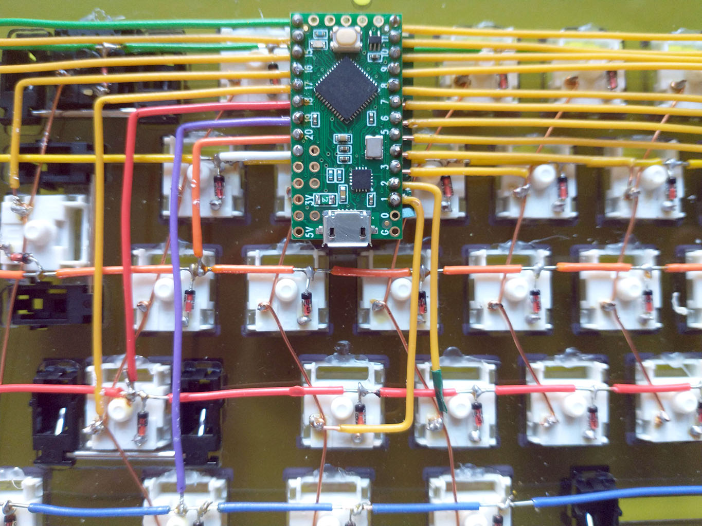
Hot tip: Don’t use cheap crappily insulated wires. Just … don’t. I bought a few spools of differently coloured silicon insulated wires but mistakenly got multicore instead of single core. Upshot though is that once you start soldering the insulation melts back. There are a couple of places I’ve had to add insulation tape to ensure no shorts.
The Beauty Shot.
Problems problems problems
Assembling the backplate to check that everything fit properly, and then trying to connect to the Teensy immediately flagged up some weird behaviour. The Teensy was periodically resetting and going into bootloader mode.
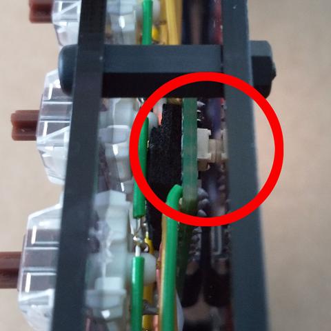
Risk Management
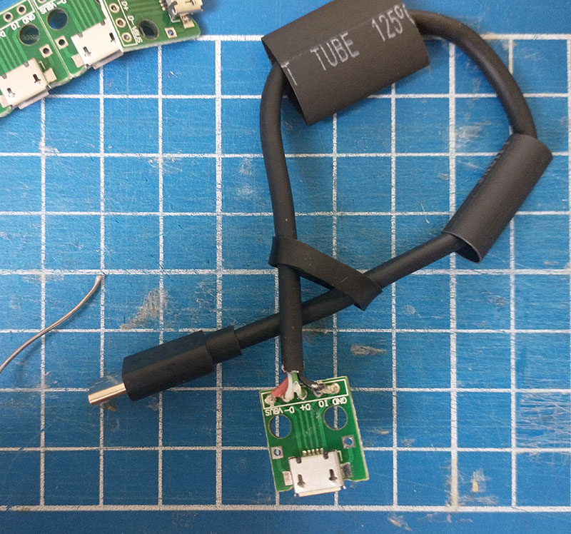
Micro USB ports on microcontroller boards anecdotally have a nasty habit of tearing right off the PCBs when stressed too much. Getting around this was the reason for the orientation of the Teensy. The last bit of soldering involved slicing up a perfectly good Micro USB cable and sticking on a USB adapter (10 pieces for a fiver) which will in turn be bolted to the base board. Reasoning being that the USB connection of a keyboard probably gets a moderate amount of stress, and replacing a 50c USB adapter is better than replacing (and resoldering) a €15 Microcontroller.
I love it when a plan comes together
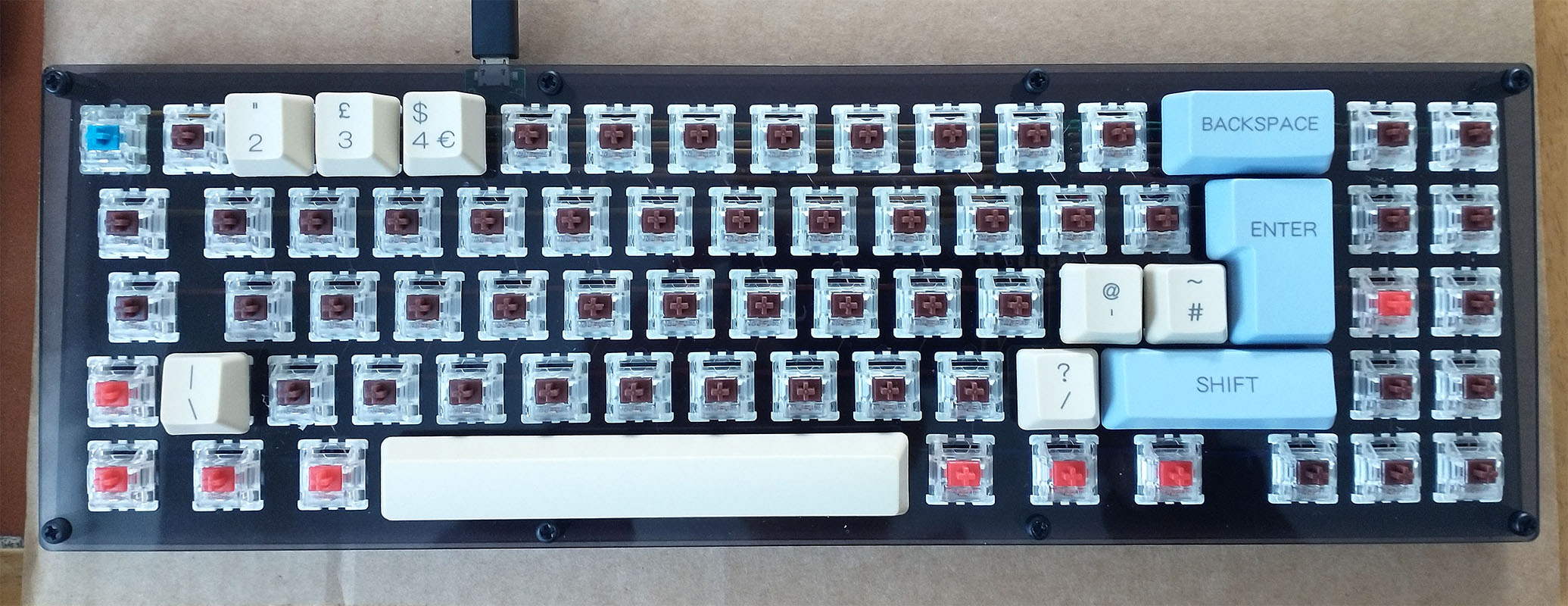
Getting the keycaps I had to get the base keycap set, and a UK ISO add on set. This is the ISO set attached, and the keys that required the stabilisers. Easier to put them on while holding the stabs in from the back of the base plate.
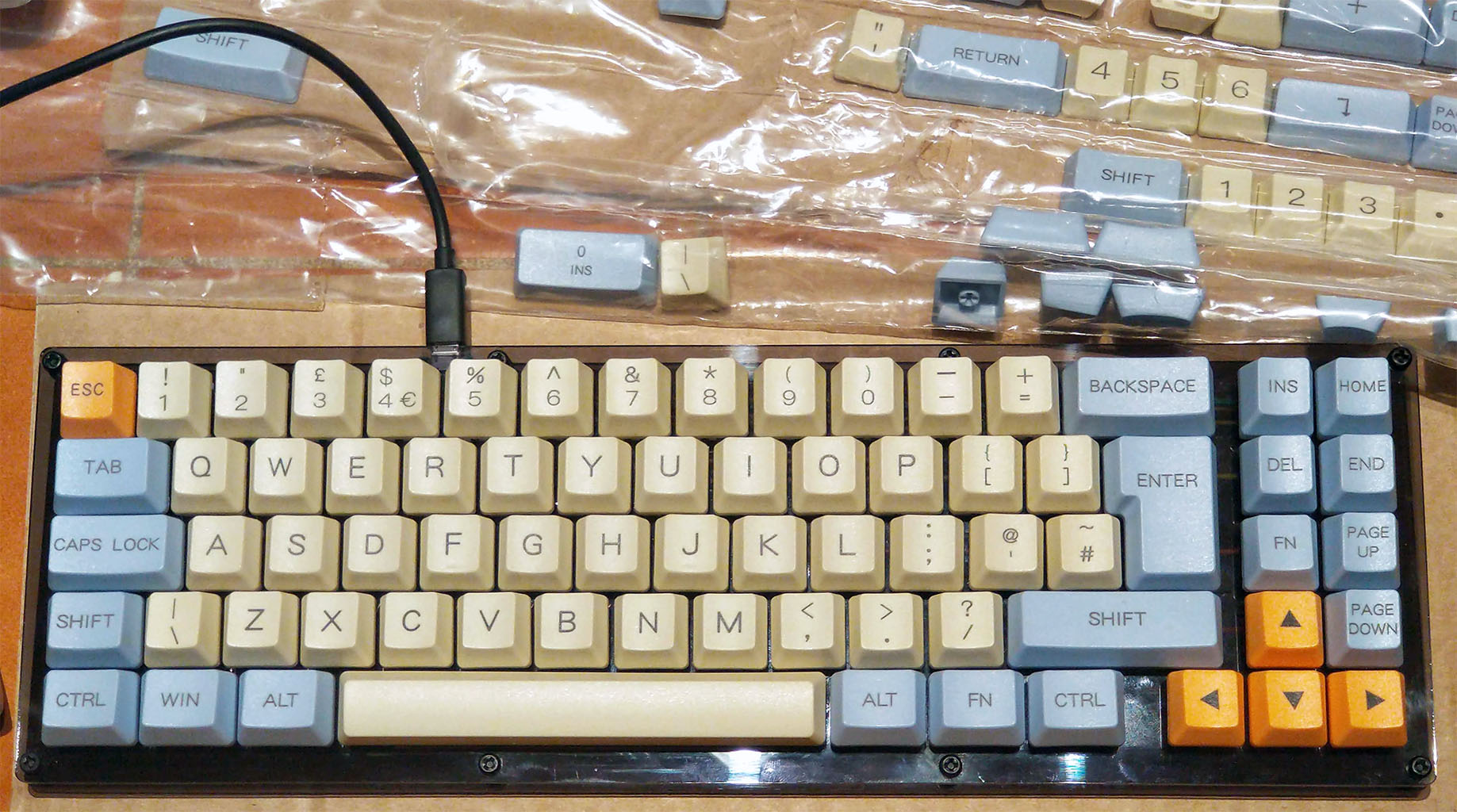
And with the full cap set:
Checking the connections
Last thing I had to do before assembling the entire board and screwing in the baseplate was check all the connections, both the Matrix connections, and the connections to the Teensy. This actually flagged up a couple of issues, and I had to go back and resolder a couple of joints. It came as no surpise to find out that it was magnet wire joints that were a bit janky, the column wires.
This is a straight matrix scan, I’ll go into more detail when I write up the Firmware post, but basically the jist is this, for the column and row pins:
Nothing fancy, we basically want to check connectivity and basic functionality. Available here
Annnnnnd, that’s that. Next up, the most interesting bit of the entire exercise, the keyboard firmware.