
The Keyboard - Part 2 : The Matrix
Wiring up the keyboard Matrix, 21 wires, 72 Diodes, and 216 solder joins later.
First, a bit of theory.
There are a few ways to wire up a bunch of switches to a microcontroller. Simplest way is the way I wired up the Multi Micro Macro, each switch connects a pin to ground, pullup resistors on the pin, and you poll the pins for state. i.e. something like …

The problem, of course, is that a keyboard has more than 6 keys. A LOT more than 6 keys. In this case 66 more keys. I’m not sure there’s a microcontroller on the market with 72 GPIO pins and even if there were I’m pretty the wiring would get out of hand pretty quickly. Luckily, this is a solved problem. The normal solution is what’s called a Keyboard Matrix which might look something like this for a 3x3 key matrix:

Rather crucially, each Row is connected to a pin, and each Column is connected to a pin, so instead of the required number of pins being == number of switches, it’s the number of rows + number of columns, or 6 pins in this case, instead of 9 if the switches were wired directly, each to a pin. Then, a row or column ‘scan’ is done, in which each of the pins in turn on (say) the Rows are pulled high, and then each Column pin is polled to check the value of that specific switch at that position. Simple, yes ? Not so fast !
Wait, What about all those Diodes ?
Ah, yes, the diodes. All 72 of them. So, as it turns out, things are not so simple. If we were dealing with only one keypress at a time then the setup above would work fine. But, this is real life, so we’re not. Multiple keys can of course be pressed simultaneously on a keyboard. With the simplistic setup above, this can cause what’s called ‘ghosting’, explained rather ably and mercifully briefly here where that scan of the matrix can give us erroneous information as to which switches are pressed. Each Switch gets a Diode wired in series, and this rather neatly solves any problem around detecting multiple keypresses:

Annd, onto more practical matters.
The general plan is to wire one set of switch pins in vertical columns, and then the other pin of each of the switches in horizontal rows, with Diodes wired in series into the row connections. There are a couple of different approaches to this, wire then insulated layers, wire with gaps cut into the insulation, small lengths of wire, etc. I chose to use magnet wire, which is single strand wire covered in an enamel insulation.
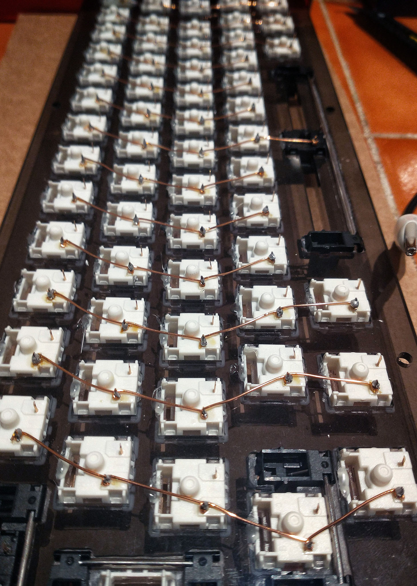
Here’s a closeup of the lower couple of rows of the board with the columns wrapped:
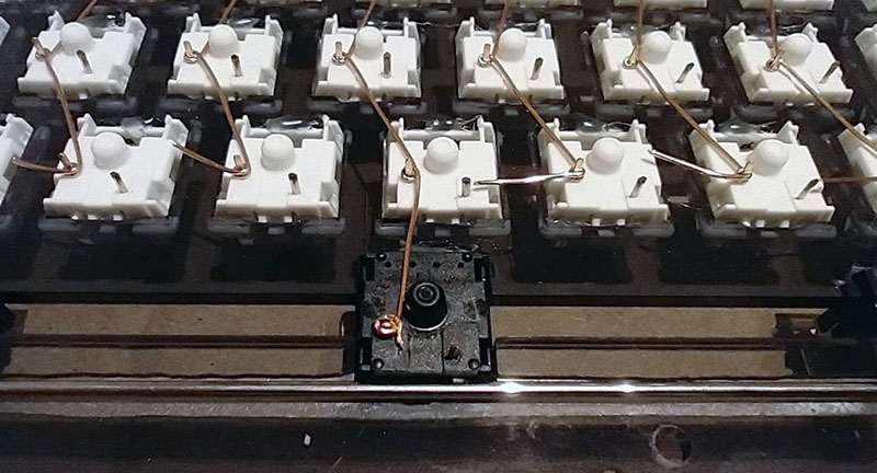
The idea being you can wrap it around each pin, then when you solder the insulation burns off just where you’ve applied the solder. Or at least that’s the plan.
And the entire board, all the columns wrapped in place, ready for soldering.
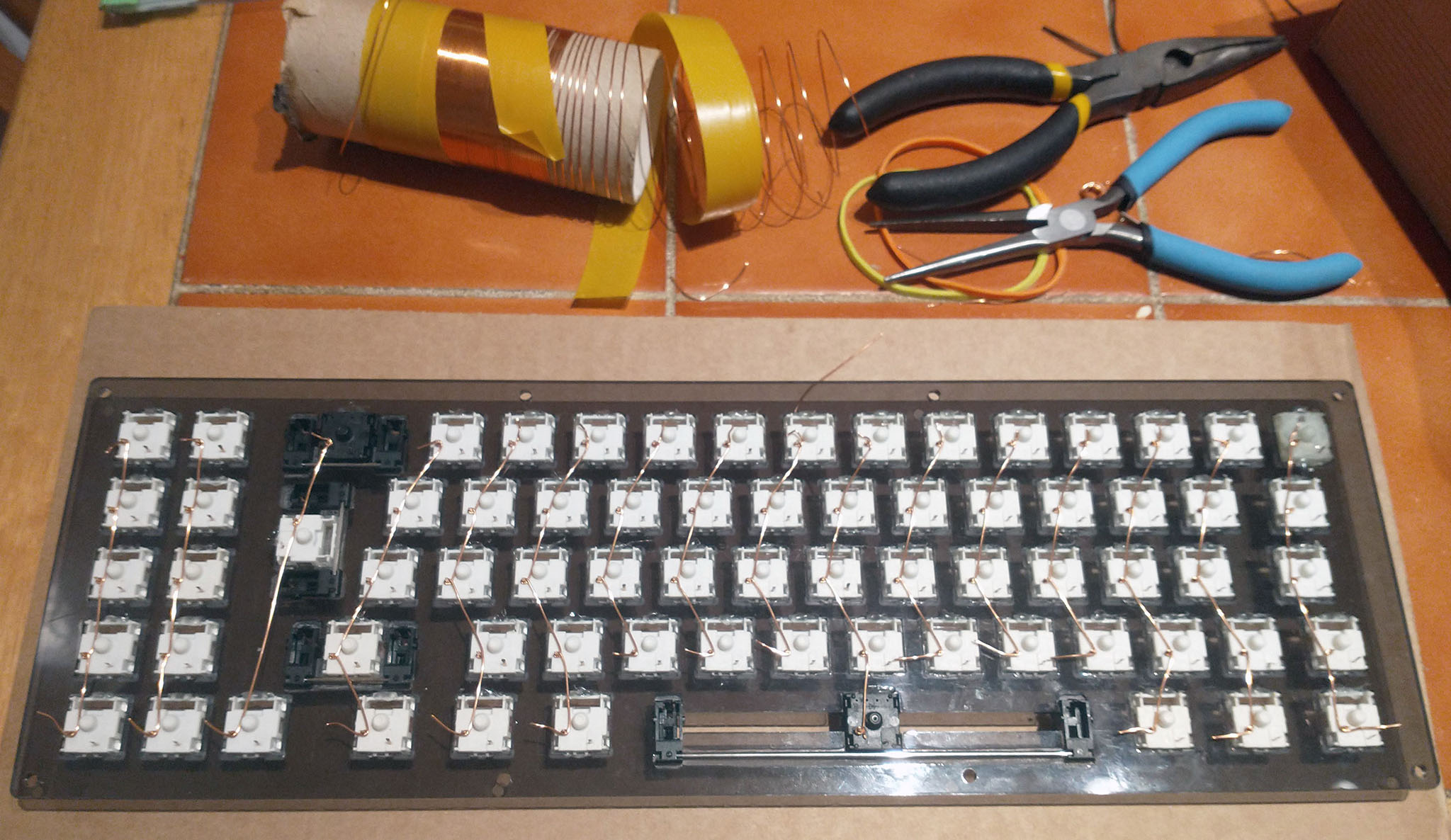
Soldering the joins turned out to be … troublesome … I had to heat up the solder to about 350c before I could get any continuity, and even at that most of the join just looks ugly. This is all columns soldered up. As each was soldered in I was doing continuity testing to make sure the joins were ok.
Soldering the rows, AKA “Ah those Diodes again”
So having finished the columns, and given the difficulty with the magnet wire, I changed tack for the rows, and went with lengths of single core with splits in the insulation. more on that in a bit. First, the Diodes had to be prepared.
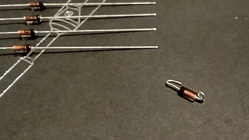
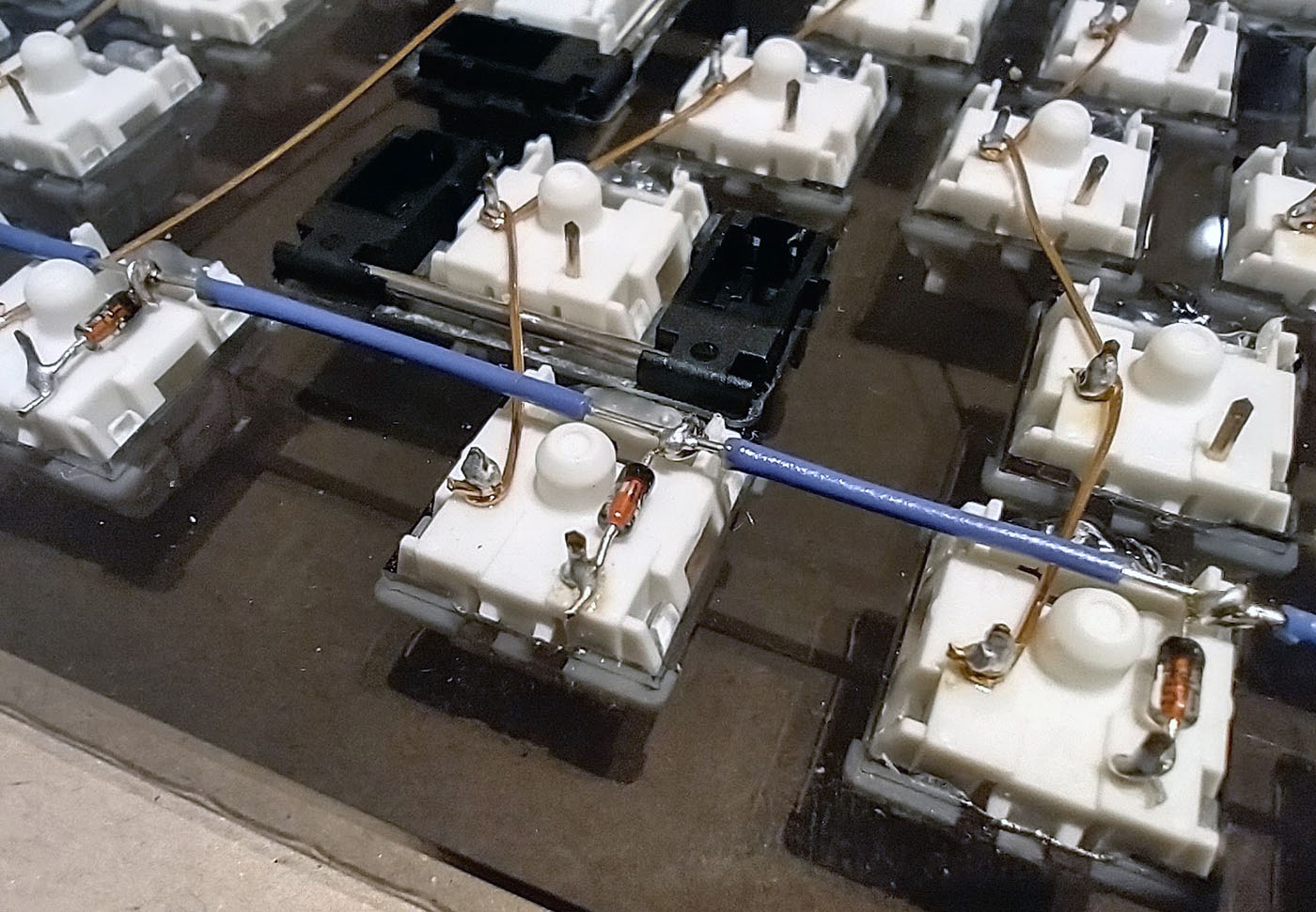
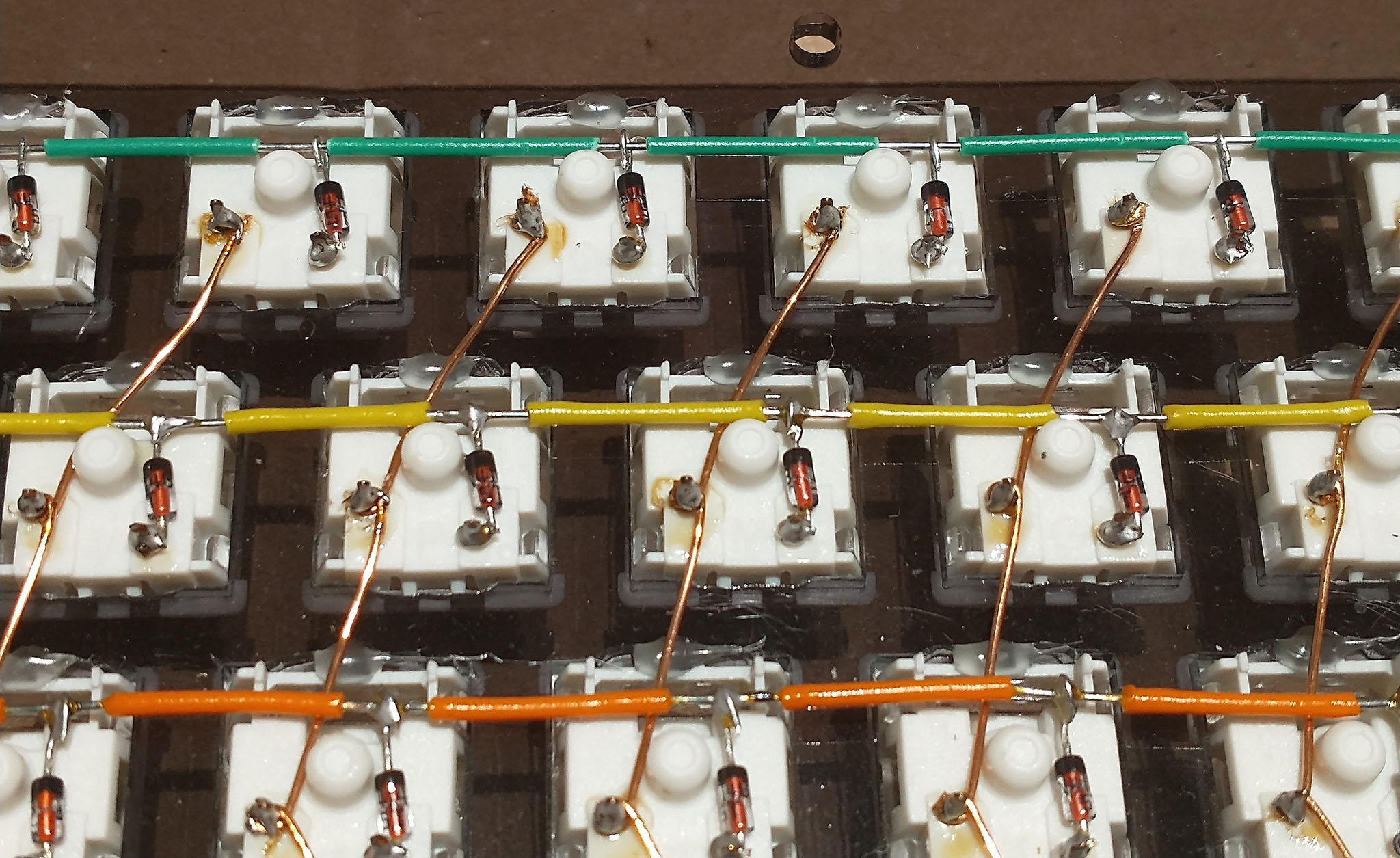
All 72 Diodes ended up getting more or less this treatment, though I eventually worked out how to do it in batches. The loop on the end got put over the switch pin, the hook is to solder in the row wire.
End result, with the row wire soldered into place, looks like so:
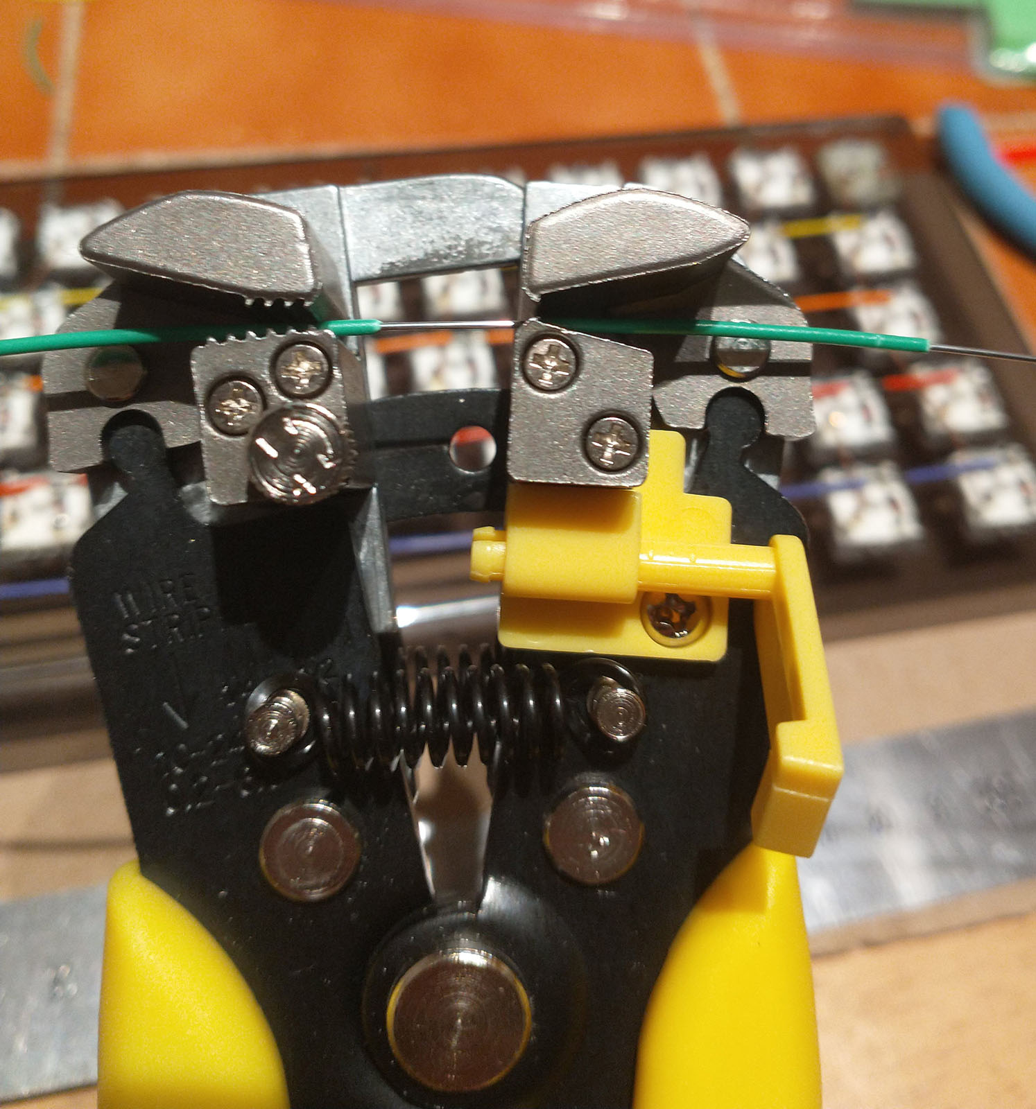
The insulation on the wire is stripped all along the wire, then hooked into the diode and soldered into place. The wire is stripped using this rather wonderful gadget, an automatic wire stripper:
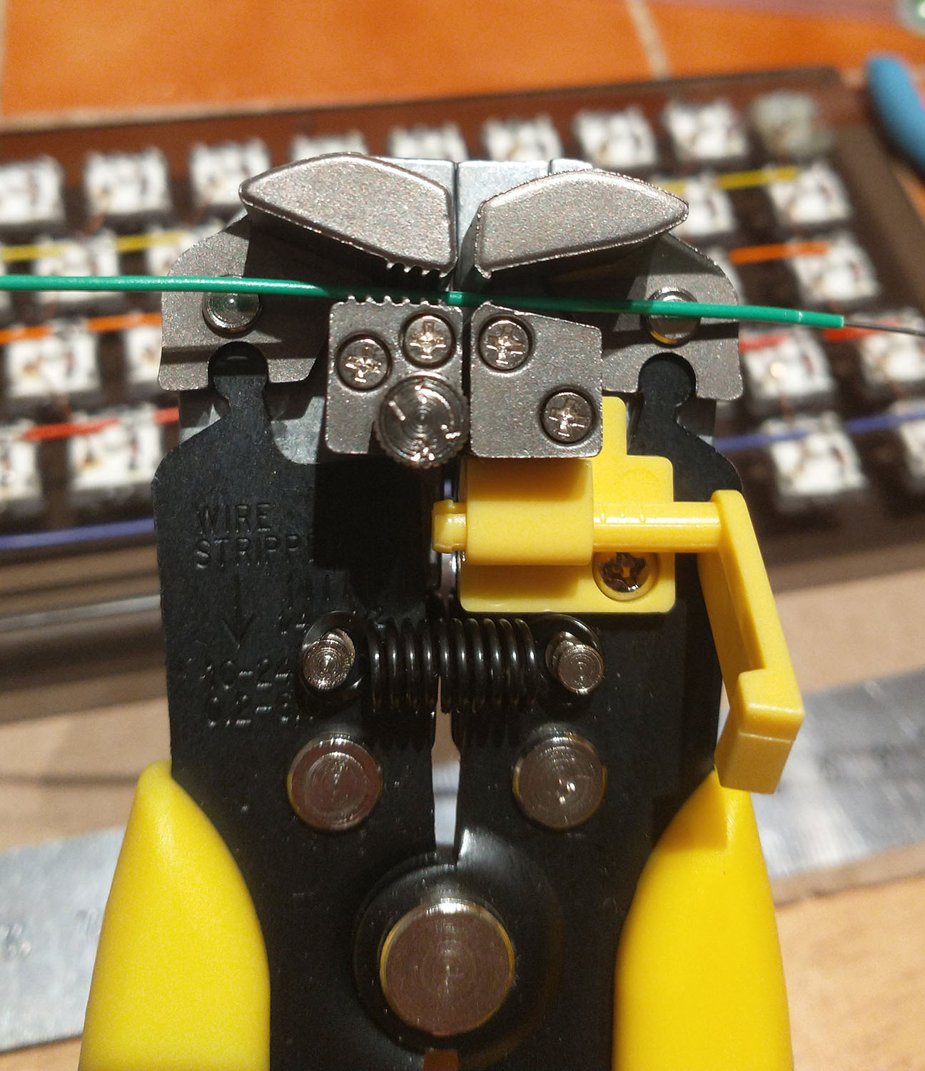
Put the wire in, squeeze, and strippppppppp ….
I measured each row, stripped off an appropriate amount from both ends of the wire, then went down the length of wire and used the stripper to strip gaps in the wire. Ultimately, after a bit of adjustment, ends up looking like this:
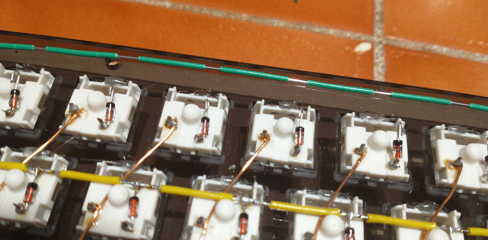
The wire hooked into the diodes and ready for soldering:
Having soldered all the diodes into place, and the row wires into the diodes, continuity testing was carried out to ensure that each row and column had connectivity and each of the switches was working (quick admission: I checked all the switches before doing any of the soldering. Pays to be sure to be sure sometimes.)
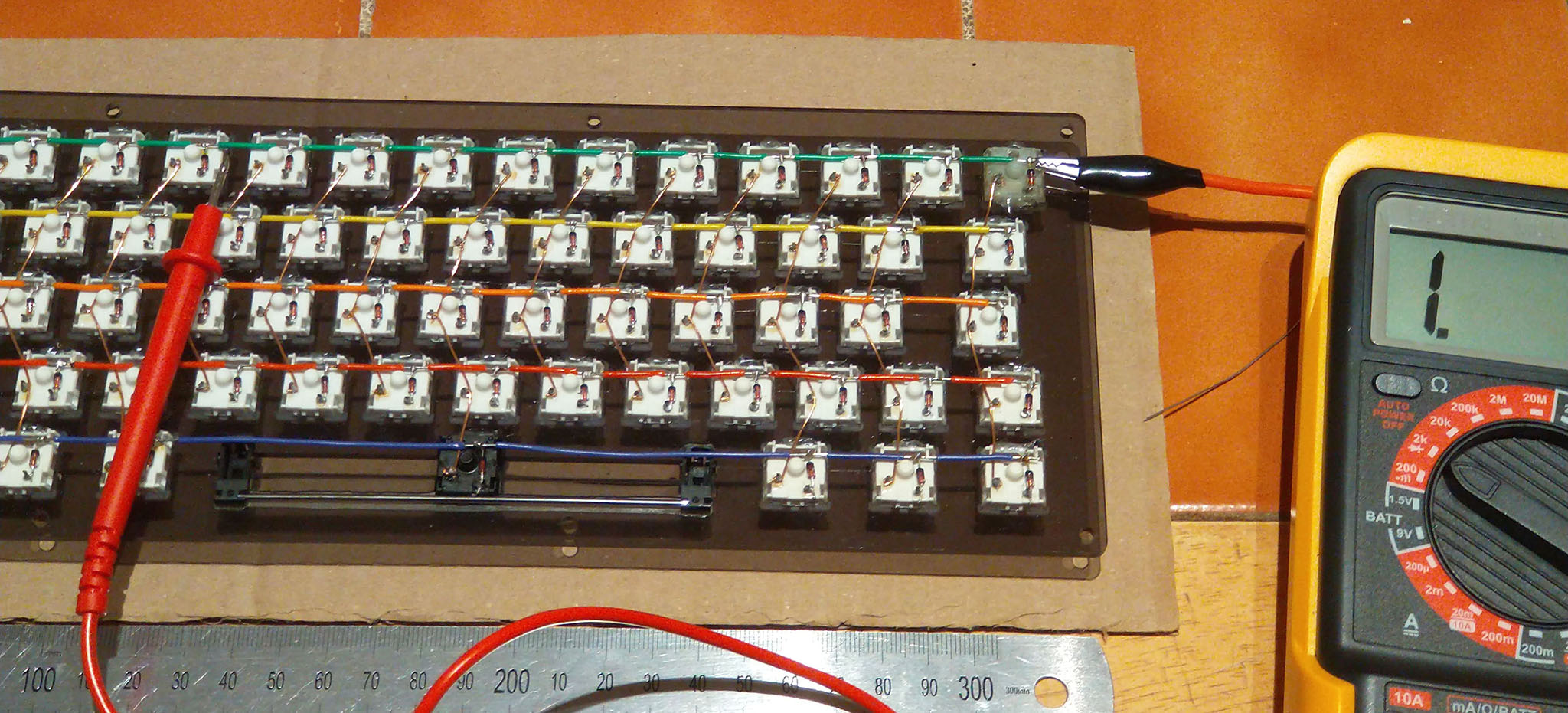
And that’s pretty much that for the Matrix wiring. There are 16 columns, and 5 rows, which necessitates 21 pins on a microcontroller. I’ve got a Teensy LC in the bag all ready to be soldered in.