
On Communication
“The more elaborate our means of communication, the less we communicate.”
Yeah, thanks Joseph Priestly. Moving swiftly along …
The importance of communication
A split keyboard is effectively two separate devices, which need to communicate keypresses to a host device. There are a couple of different ways to make this happen:
- Both halves plugged into two separate USB ports on the computer, or into a hub which is then plugged into the computer, this is where we left the split in the last post.
- Have one half as the Primary, which communicates with the host device, and ALSO orchestrates data from the Secondary half.
The most common method is the 2nd, for a couple of reasons. One is so that there’s only one cable from the board to the host device (though another connecting the two halves of the board), and another is that various special layer effects and Fn mappings and so on can affect both halves of the keyboard, which wouldn’t be the case if both halves were independent keyboards on the system.
Actually there is another way of connecting the two halves, one microcontroller in one half, and the entire row and column matrix wiring extended across the two halves, it’s unpopular in the common case because anything from 12 to 16 wires would be needed to connect the halves. OTOH in the case of simple 40s it’s possible
Having decided on the connection method, there are a few common communication protocols that you can use to get a couple of microcontrollers talking to one another.
- UART the classic rx/tx serial interface, simple and well documented, no clock line, can’t trivially have multiple devices on a bus.
- SPI Faster than I2C & UART, no problems with addressing devices BUT, needs at least 4 lines, and every new device needs an extra address line so each device needs to be wired up individually.
- I2C or IIC, for Inter Integrated Circuit, was designed specifically for microcontrollers. Only 2 lines for communication, and multiple devices can be chained on the bus. It is slower than SPI, and an errant device on the bus can hose the entire communication.
I went with I2C as it seemed easier to wire up (4 wires from Primary->Secondary including VCC and GND) and I had a plan to potentially extend the bus to allow more devices communicate on it, or for the Primary to push events and notifications to other devices i.e. screens, or speaker device, etc etc.
Wiring it up

Wiring it up is easy, GND and VSYS on the Primary to GND and VSYS on the Secondary, to provide power, and the I2C lines from the Primary to the Secondary to provide the communication link. No extra pullups were added, I assumed the internal pullups would ensure it would behave. So far it hasn’t been a problem.
Physically, I used these nifty 4 pin aviator connectors, and a custom coiled cable, to connect the two halves.
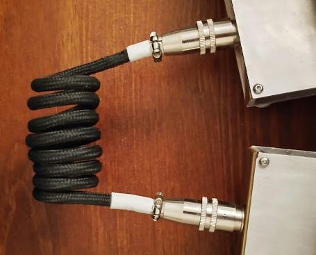
They’re push-pull connectors so the Secondary half can be disconnected entirely if necessary. The cable was coiled in the same way as the cable here, then the individual lines soldered into the aviator connectors and heat shrink applied before the entire thing was screwed together.
The Firmware
Obviously, firmware updates had to be made to support this new split layout. The plugin architecture of my firmware proved up to the job. This is a rough diagram of how it worked out (details follow):
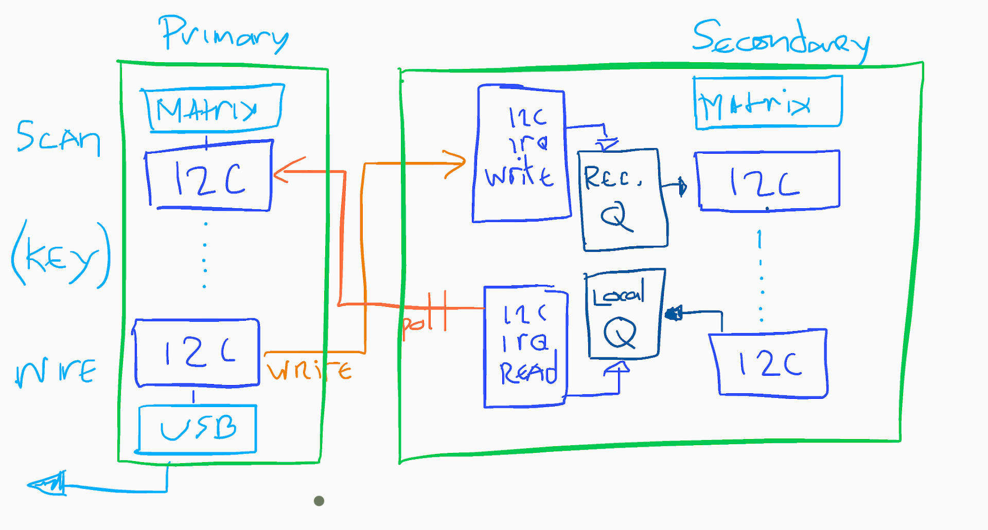
Ehhh, ok so lets dig into this a bit. The crucial part is that the entire I2C stack is handled by one plugin, the I2CWireHandler, which extends both the InputDevice AND WireHandler base classes, so effectively can act as a source of events, but also sit at the end of the event chain and forward on events to their final destination.
The Primary, in its WireHandler writes events to the Secondary, so long as their source is not the Secondary. In its InputDevice it polls the Secondary for any events.
The Secondary maintains an IRQ handler which responds to write requests from the Primary by putting the events into a Receive Queue, and responds to read requests from the Primary by writing out the contents of its Local Queue, followed by a null ’empty’ event to signify the end of the write.
On the Secondary, The Receive Queue is consumed by the InputDevice, and the events put onto the event stack, and the Local Queue is populated by the WireHandler. The Primary then polls and consumes these events as above.
The I2CHandler Plugin
This is the class definition:
#define LOCAL_I2C_ADDRESS 0x00
#define PRIMARY_I2C_ADDRESS 0x75
#define SECONDARY_I2C_ADDRESS 0x76
#define I2C_TIMEOUT_US 100000
#define I2C_BUS_SPEED 100000

class I2CWireHandler : public InputDevice, public WireHandler {
    public:
        I2CWireHandler(bool primary);
        bool inputEvent(InputEvent* event, KeyboardState* kbState);
        bool scan(KeyboardState *keyboardState);
    private:
        unsigned int busSpeed = 0;
        bool primary = true;
};
We’ve defined (pretty arbitrary) I2C addresses, and we can see that the I2CWireHandler extends both the InputDevice and WireHandler base classes.
This is the Constructor code for the plugin:
I2CWireHandler::I2CWireHandler(bool primary):WireHandler() {
    printf("Initialising I2C Wire Handler");

    //setup the I2C bus on the Pico
    busSpeed = i2c_init(i2c1, I2C_BUS_SPEED);
    gpio_set_function(27, GPIO_FUNC_I2C);
    gpio_set_function(26, GPIO_FUNC_I2C);
    gpio_pull_up(27); //TODO: make these pins configurable.
    gpio_pull_up(26);

    this->primary = primary;
    if(!primary) {
        //The Secondary half has a lot more set up to do.
        //Firstly, it's put into slave mode, and needs an I2C address.
        i2c_set_slave_mode(i2c1,true, SECONDARY_I2C_ADDRESS);

        // Enable the I2C interrupts we want to process
        i2c1->hw->intr_mask = I2C_IC_INTR_STAT_R_RX_FULL_BITS | I2C_IC_INTR_MASK_M_RD_REQ_BITS;
        // Set up the interrupt handler to service I2C interrupts
        irq_set_exclusive_handler(I2C1_IRQ, i2c1_irq_handler);

        //setup queues for the secondary, local queue to hold events for the
        //primary to query, and the received queue to hold events SENT by the
        //primary that we'll put through the inputEvent queue in the scan method.
        queue_init(&localEventQueue, sizeof(class InputEvent), 10);
        queue_init(&receivedEventQueue, sizeof(class InputEvent), 10);
        // Enable I2C interrupt
        irq_set_enabled(I2C1_IRQ, true);
    }
}
This handles the initialisation, and setting up the Interrupt Request handler for the Secondary side. The two queue objects are created on the Secondary to store the received and local events, more on this in a bit.
On the Primary
On the Primary half of the keyboard, the behaviour is pretty straightforward. There are two parts to it, the ‘InputDevice’ part and the ‘WireHandler’ bit. This is the ‘WireHandler’ code on the Primary with the Secondary specific code removed:
bool I2CWireHandler::inputEvent(InputEvent* event, KeyboardState* kbState) {
    //if MASTER then we send the event to the secondarys IFF the source isn't
    // already the secondary.
    //if SECONDARY then we add to a buffer and wait for the MASTER to call
    //the SCAN method as below at which point the buffer will be dumped
    //out to master.
        .
        .
        .
            printf("Primary\n");
            if (event->source != SECONDARY_I2C_ADDRESS) {
                int connStatus = i2c_write_timeout_us(i2c1, SECONDARY_I2C_ADDRESS, (uint8_t *)event,sizeof(class InputEvent),false,I2C_TIMEOUT_US);
                if (connStatus == PICO_ERROR_GENERIC) {
                    printf("I2C ERR\n" );
                } else if (connStatus == PICO_ERROR_TIMEOUT) {
                    printf("I2C Timeout\n");
                } else {
                    printf("sent %d to secondary. Bytes: %d. Sizeof: %d \n", event->scancode, connStatus, sizeof(class InputEvent));
                }
            }
        .
        .
        .
    return true;
This happens after all the Key Plugins have been called, but before the USB Wire Handler, it sends every event onto the Secondary half, so long as the event hasn’t originally COME from the Secondary (i.e. the Event Source is not equal to the SECONDARY_I2C_ADDRESS above). It returns ’true’ so the event will be forwarded onto the USB handler to be sent to the host device.
The InputDevice on the Primary is a little more complicated, it consumes Events from the Secondary by reading events on the I2C bus, until it receives an event with a 0 valued scancode signifying an empty event. This is sent by the Secondary to indicate there are no more events to be read.
InputEvent event;
//we'll do a read timeout here in case the bus goes down, but the
//way this is _supposed_ to work there will always be an event on
//the secondary to query
int returned =  i2c_read_timeout_us(i2c1, SECONDARY_I2C_ADDRESS, (uint8_t *)&event,sizeof(InputEvent),false,I2C_TIMEOUT_US);
if (returned == PICO_ERROR_GENERIC) {
            //printf("I2C ERR\n" );
} else if (returned == PICO_ERROR_TIMEOUT) {

} else {
    //IFF it's an actual keycode, then we can get a proper input event
    //from our pool, copy this event into it, and pass it up the chain.
    if(event.type == SCANCODE) {
        while (event.scancode != 0) {
            printf("event %d : %d \n",event.scancode, event.state);
            InputEvent* inputEvent = keyboardState->inputEventPool.getInputEvent(event);
            keyboardState->inputEvent(inputEvent);
            i2c_read_timeout_us(i2c1, SECONDARY_I2C_ADDRESS, (uint8_t *)&event,sizeof(InputEvent),false,I2C_TIMEOUT_US);
        }
    }
}
If the event is a valid event then an inputEvent is fetched from the pool, setup, and put onto the event stack through the keyboardState.
Given that the Secondary is polled every time there’s a scan on the Primary, it’s entirely expected that the vast majority of requests will just result in an empty response i.e. an initial event scancode = 0 indicating a no-op.
On the Secondary
The behaviour on the Secondary is a little more convoluted. The I2CHandler on the Secondary is entirely IRQ driven. The IRQ Handler is triggered on both read and write requests from the Primary. Two circular queues are maintained, with a static capacity of 10 events.
- The Receive Queue is written to by the IRQ Handler on a ‘Write’ event from the Primary, and read from by the InputDevice code on the Secondary.
- The Local Queue is written to by the WireHandler code in the Secondary, and read from in the IRQ handler on a ‘Read’ event from the Primary, at which point the events are communicated to the Primary.
The queue implementation in the Pico SDK is Multicore and IRQ safe.
Secondary IRQ Handling
The IRQ code is pretty straightforward;
// Get interrupt status
    uint32_t status = i2c1->hw->intr_stat;
    //is a write request? Or a read request ?
    if (status & I2C_IC_INTR_STAT_R_RX_FULL_BITS) {
        //this is a write IRQ from the primary, so 1st create an event object
        InputEvent event;
        //now read from the bus into it
        i2c_read_raw_blocking(i2c1, (uint8_t *)&event, sizeof(class InputEvent));
        //set the source to the PRIMARY
        event.source = PRIMARY_I2C_ADDRESS;
        //and finally add the event to the Receive Queue
        queue_try_add(&receivedEventQueue, &event);
    } else if (status & I2C_IC_INTR_STAT_R_RD_REQ_BITS) {
        //this is a read IRQ from the Primary.
        //Create an empty event here, if the queue is non empty then
        //it'll be populated with the head of the queue, otherwise
        //we'll just send the empty event, which will make Primary stop
        //requesting events.
        InputEvent event;
        if(!queue_is_empty(&localEventQueue)){
            //pop the head of the queue off and load up the event with it.
            queue_try_remove(&localEventQueue, &event);
        }
        //set the event source to the SECONDARY, and write the event
        //to the I2C bus. Then clear the IRQ.
        event.source = SECONDARY_I2C_ADDRESS;
        i2c_write_raw_blocking(i2c1, (uint8_t *)&event, sizeof(class InputEvent));
        i2c1->hw->clr_rd_req;
    }
Depending on whether it’s a write or read IRQ it either grabs the event from the bus and loads it into the Received Queue, or writes out the head of the Local Queue to the bus. The Primary will continue requesting events until it gets the empty event, which the Secondary sends above if the Local Queue is empty.
InputDevice and WireHandler methods
Then similarly to the Primary, there are the two methods for the InputDevice and WireHandler behaviour. In the case of the Secondary, they involve reading from or writing to the appropriat Queue.
In the ‘inputEvent’ method, which is the WireHandler method, and called at the end of the event stack, the implementation is simple:
    if (event->source != PRIMARY_I2C_ADDRESS) {
        queue_try_add(&localEventQueue, event);
    }
If the event didn’t COME from the Primary, then it gets put onto the Local Queue, where the Primary will pick it up in its InputDevice pass.
The ‘scan’ method, which is the InputDevice method, responsible for putting events ONTO the event stack, reads from the Received Event Queue, and calls the inputEvent from the KeyboardState object if appropriate, putting the event on the event stack.
    InputEvent event;
    while (!queue_is_empty(&receivedEventQueue)){
        //pop the head of the queue off and load up the event with it.
        queue_try_remove(&receivedEventQueue, &event);
        //load into event from the pool and call into the keyboard state.
        InputEvent* inputEvent = keyboardState->inputEventPool.getInputEvent(event);
        keyboardState->inputEvent(inputEvent);
    }
Links to the complete firmware, and to the I2CWireHandler code.
Conclusion
Briefly, this board has been my main dev board for the last few months, and hasn’t failed or skipped a character or hung up even once, so I’ve been impressed by its resilience.
Alternative strategies
This took a bit of messing around to actually get into a working state. Coming from a position of almost complete ignorance about I2C, I tried a couple of different approaches before settling on this one. The empty event as a signifier to the Primary that there is nothing to read from the Secondary isn’t ideal, I had tried the i2c_get_read_available at one point, and also, when that didn’t work, the i2c_read_timeout_us with a sufficiently small timeout that if there was nothing to read the Primary would just continue on its way. Neither worked, the ‘read_available’ was always 0, the read_timeout would hang IIRC so I settled on this mechanism instead.
Building out
The I2C communications was the first big test to prove out the applicability of the plugin based firmware I’ve put together for the Pico (and could be adapted to the Teensy code as well given a bit of work). Ultimately the plan was to be able to put other devices on the I2C bus as well, a display perhaps, or a BLE breakout to build a wireless board. There’s always just one … more … board … to build …