
Split 65 Build
Building a Split 65(ish)% Ergonomic board, part 1.
Round about when I finally finished the original keyboard and firmware, Raspberry Pi released the Pico , a new Microcontroller. Dual core ARM M0+, lots of memory and program space, LOTS of GPIO (26 pins in total) and USB device/host support. All for €4. I immediately bought 2, then decided what to do with them. The answer ? A split ergonomic keyboard of course. Back to the Keyboard Layout Editor!
Requirements
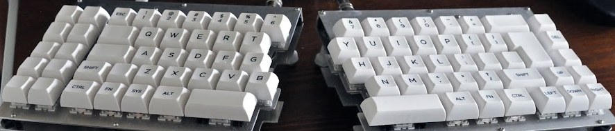
I wanted a fairly conventional layout, similar to the previous board, but more compact on the right hand side, and with a column of function keys to balance out the left. I wanted a board that could be fit back together with a minimum of fuss so that, if necessary, I could just treat it as a normal keyboard. This was the eventual layout (with both sides combined):

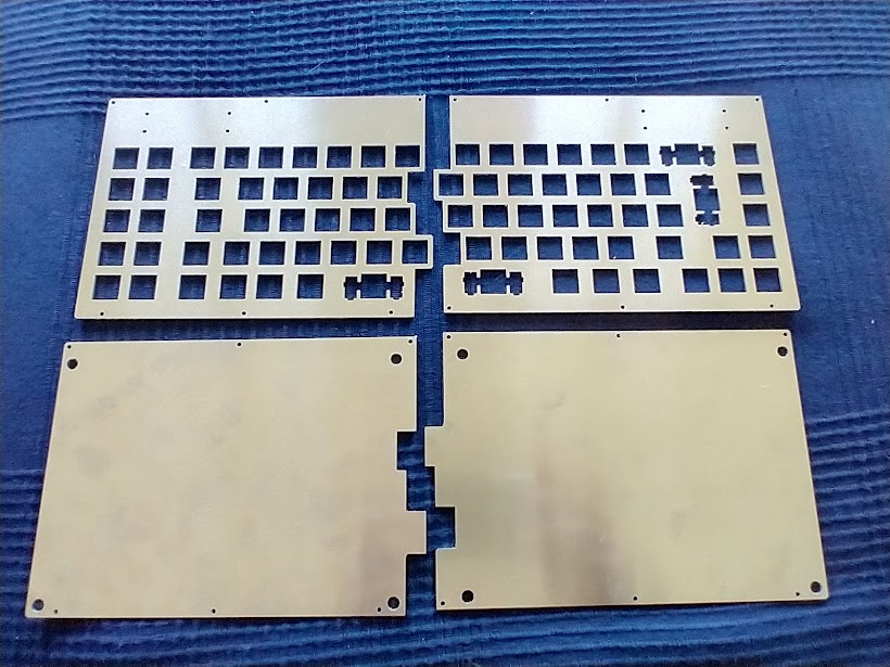
I took the JSON from the Keyboard Layout Editor, and used swillkb Plate and Case builder to create an initial SVG for the top and bottom plates. These of course weren’t yet split. I used Inkscape to laboriously draw a split path down the plate between the appropriate keys, used the same path on the bottom plate, and the eventual top and bottom plates (with mounting holes for the PICOs added as well) looked like this:

The larger holes on the bottom plate are to allow for tenting adjusments, more on that later.
I got the plate cut through an online place, https://laserteileonline.de/ which seemed to be the cheapest place to get a 1.5mm Aluminium plate done. Getting one offs done is not cheap. The plate cost a little under €60 including postage. I definitely have to rope more people into this next time ‘round …
Ah Switches, Switches, Switches
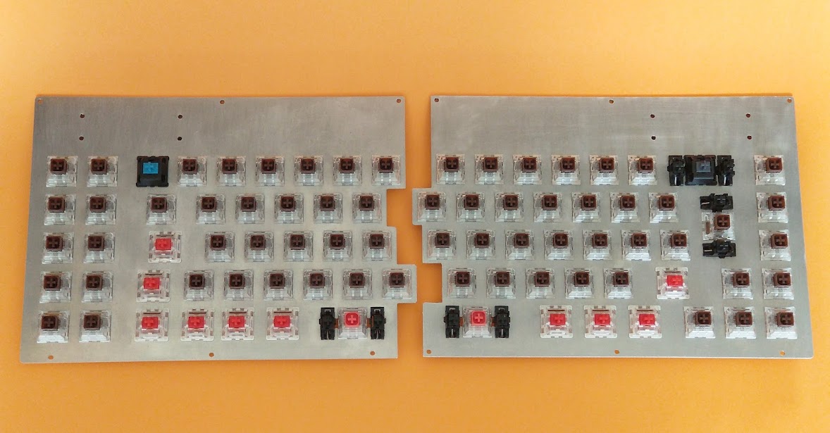
Emboldened by my previous board, I decided to go with a mix of tactiles and linears for this board. Kailh Box Browns for the alphas/punctuation, heavy burnt oranges for the space bars, linear reds for the mods. Plus, as with the last board, a nice clicky blue for the ESC key, and a silent grey for the backspace.
Bought these, and a bunch of cherry stabilisers, from KBDFans on Aliexpress,
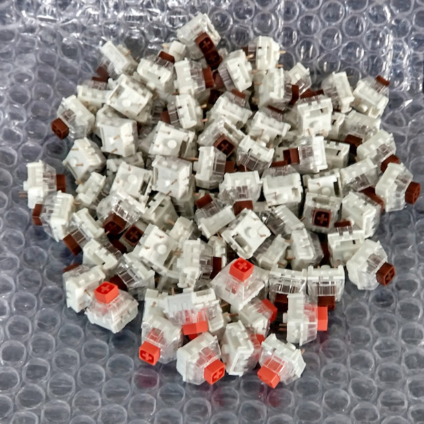
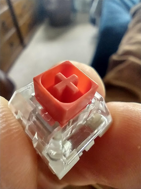
The burnt oranges in particular have such a pronounced and lovely tactile bump right at the top of the swich that one lives on my desk as a fidget toy
Wasted no time getting the switches popped into the plate, and the stabilisers in place.
Time to get wiring…
Handwiring / rows / columns / Pico
Wiring followed roughly the same pattern as the last board and wiring up the microcontroller with a couple of exceptions. This time round I dispensed with the magnet wire on the columns and just used normal wire, and I also mounted the PICO before doing the wiring, bending up the end of the wire and soldering the ends into the GPIO contacts as I went. Eh … voila:
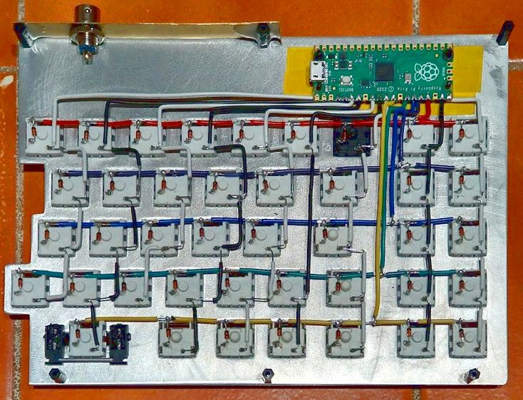
This is all 9 columns and 5 rows of the left hand side wired into the Pico for a total of 14 pins. This rather neatly all fits on one side of the Pico, leaving the other side free to wire up I2C, or SPI, or UART, or whatever. We’ll be using it for I2C anyhow, to connect the two halves of the keyboard.
Port at the top left is the socket half of a 4 pin aviator connector, which will be wired up via I2C to connect the split.
Ok, so quick segue, the very first thing I did was to flip that over, bolt the bottom half of the plate on, put the keycaps on, and connect it up so I could download a really barebones switch tester to the board, something similar to what I describe at the end of this post.. This was just to verify that the soldering was all ok, the Pico working correctly, the switches all working, etc etc.
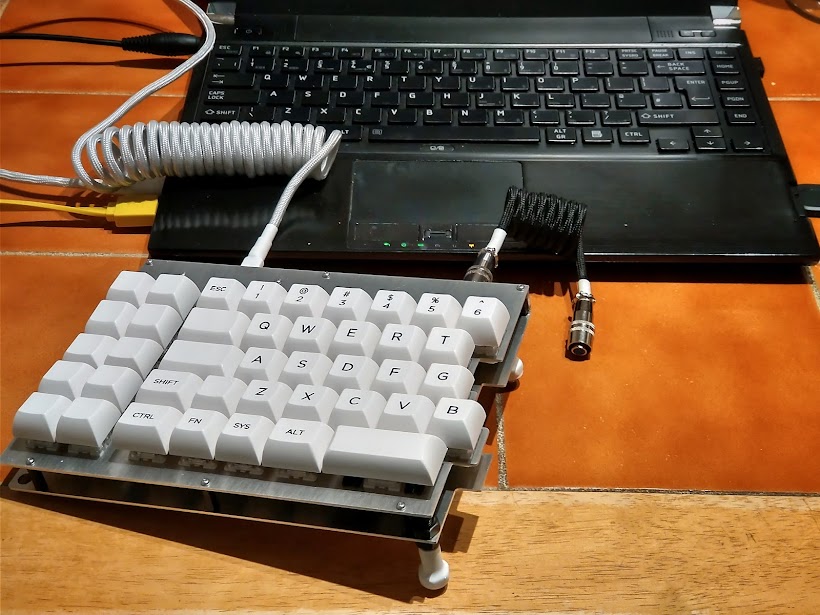
Just stop for a moment and look at those keycaps. Gorgeous clean BOW KAT Alpha caps. MMmmm.
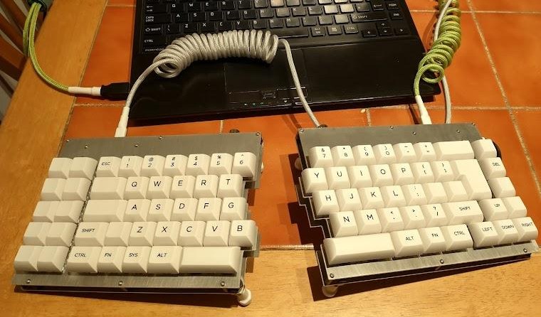
Right hand side was much the same, wired up rows/columns, added the keycaps, uploaded the same firmware check to the board. At this point I forked the existing firmware onto a Pico branch on github…
https://github.com/dairequinlan/mechware/tree/pico
… and started making sense of the (very well documented) Pico SDK. Getting a functional firmware up and running was reasonably straightforward, some syntax changes, different includes, and a significantly different wire handler for the USB. This was all handled through a combination of conditional compilation and different plugins.
The original Teensy/Arduino code just used the normal Arduino Keyboard library to handle the keypress and release USB communications. The Pico SDK relies on a library called TinyUSB for its USB communications, so the PICO board got its own wire handler, the TinyUSBWireHandler that it uses as a wire plugin instead of the USBWireHandler used on the Arduino boards. It has to handle a lot of the key state and USB HID info internally.
So at this point I had both halves working as independent keyboard devices, connected via USB to a laptop.
The next job (and the subject of the next blog post) was to work out how to get both halves to talk to one another …